![]()
Pump Selector Calculation
Contents of this page:
Minor Loss Coefficient Calculator. Enter the number of elbows, valves, fittings, etc. that exist on the suction and discharge pipelines. The calculation computes the sum of the minor loss coefficients for each pipeline. These sums (Ks and Kd) are then entered into the second calculation.
Pump Selector Calculator. Computes Total Dynamic Head (TDH) and Net Positive Suction Head Available (NPSHA) for a piping system, then determines which pumps in the Master Pumps database satisfy the pump type, capacity, TDH, temperature, and NPSH requirements for the system.
Discussion Piping Scenarios Equations Variables Error Messages References
Minor Loss Coefficient Calculator
Enter the number of fittings of each type on the suction and discharge sides of the
pump. The sum of the minor loss coefficients is computed and entered manually in Pump Selector Calculation that follows. Minor
loss coefficients were obtained from Mays (1999).
Discussion
To top of page
The pump selector calculation lists up to nine
pumps from the database that match the following criteria. To be listed, a pump
must:
· Be the type of pump that the user selects.
· Must have a maximum capacity greater than the system requirement and less than 1.25
times the system requirement.
· Must be able to supply a maximum TDH greater than the system requirement but less than
1.25 times the system requirement.
· Must have an NPSH requirement less than the NPSH available.
· Must have a maximum temperature rating higher than that of the liquid being pumped.
Pumps are sorted in order of increasing price.
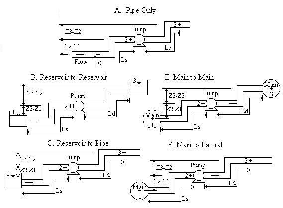
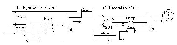
Piping Scenarios
To top of page
Terminology:
"Main" can physically represent several different things: It could be a
water main or any large diameter pipeline having a smaller diameter pipe (a lateral) that
branches off of it. It could also be a tank that is under pressure.
"Reservoir" is a tank or lake whose surface is open to the atmosphere. The calculation automatically sets a reservoir's pressure (P1 or P3) to 0. Note that a reservoir is a main with a pressure of 0.
In all scenarios, flow is from 1 to 3. It is okay if Z2-Z1 and/or Z3-Z2 is negative.
Equations
To top of page
The following equations are the standard equations for flow of viscous fluids. They
can be found in many fluid mechanics textbooks, some of which are listed in references. The Darcy-Weisbach friction loss method is used
because it allows major losses (pipe friction) to be determined for any fluid.
Horsepower and Affinity Laws (0.7 is efficiency, D is impeller diameter):
Variables
To top of page
[] indicates units: [L] means variable has units of length, [F] force, [M] mass, [P]
pressure, [T] time, [t] temperature.
Heads are typically expressed in length units, such as ft. However, they can be
expressed in pressure units such as psi (by multiplying the head by the weight density, W,
of the fluid). Likewise, pressures can be expressed in units of head (by dividing by
the fluid's weight density).
Subscripts:
1 indicates location 1. 2 indicates location 2 (pump inlet).
3 indicates location 3.
s indicates the suction pipeline (pipe and fittings between locations 1 and 2).
d indicates the discharge pipeline (pipe and fittings between locations 2 and 3).
As = Cross-sectional area of suction pipeline [L2].
Ad = Cross-sectional area of discharge pipeline [L2].
d = Density of water at standard conditions = 1000 kg/m3.
Ds = Inside diameter (ID) of suction pipeline [L].
Dd = Inside diameter (ID) of discharge pipeline [L].
e = Roughness of pipe surface [L].
fs = Suction side Darcy-Weisbach friction factor. Determined
from Moody diagram or equations.
fd = Discharge side Darcy-Weisbach friction factor. Determined
from Moody diagram or equations.
g = Acceleration due to gravity = 9.8066 m/s2. = 32.174 ft/s2.
hs = Suction side pipeline minor losses [L]. This is due to
valves, pipe bends, and other fittings.
hd = Discharge side pipline minor losses [L]. This is due to
valves, pipe bends, and other fittings.
Hs = Suction side pipeline major losses [L]. Due to friction
between the inside pipe walls and the flowing fluid.
Hd = Discharge side pipeline major losses [L]. Due to friction
between the inside pipe walls and the flowing fluid.
Ks = Sum of minor loss coefficients due to valves, pipe bends and
other fittings on suction pipeline.
Kd = Sum of minor loss coefficients due to valves, pipe bends and
other fittings on discharge pipeline.
Ls = Length of suction side pipeline [L].
Ld = Length of discharge side pipeline [L].
NPSH = Net positive suction head [L]. The calculation computes NPSHA
(NPSH available), whereas pumps have a certain NPSHR (NPSH required). For
a pump to operate successfully, NPSHR must be <= NPSHA.
Patm = Atmospheric (or barometric) pressure [P]. Standard
atmospheric pressure = 14.7 psi = 29.92 inch Hg = 760 mm Hg = 1 atm = 101,325 Pa = 1.01
bar. Note that your local atmospheric pressure is different from standard
atmospheric pressure.
Pv = Vapor pressure of fluid [P]. Expressed as an absolute
pressure.
P1 = Gage pressure at location 1 of the system [P]. Location 1
could be the surface of a reservoir open to the atmosphere (thus P1=0),
or the pressure in a supply main (same as a tank under pressure), or location 1 could
simply be a location in a pipe upstream of the pump.
P3 = Gage pressure at location 3 of the system [P]. Location 3
could be the surface of a reservoir open to the atmosphere (thus P3=0),
or the pressure in a supply main (same as a tank under pressure), or location 3 could
simply be a location in a pipe downstream of the pump.
Re = Reynolds number. Indicates whether flow is laminar or turbulent and is
used to compute f.
Q = Flowrate (or capacity) of the fluid flowing through the pipe system [L3/T].
S = Specific gravity of the fluid.
T = Fluid temperature [t].
TDH = Total dynamic head [L].
Vs = Velocity in suction pipeline [L/T].
Vd = Velocity in discharge pipeline [L/T].
V1 = Velocity of fluid at location 1. This is determined when
you select a scenario. If location 1 is a reservoir or main (Scenarios B, C, E, and
F), then V1 is automatically set to 0 because the velocity head of the
fluid in the reservoir or main (or pressure tank) is much smaller than in the attached
pipeline. This is a standard assumption in fluid mechanics. However, if
location 1 is inside your suction side pipeline of diameter Ds, then V1
is automatically computed as Q/As.
V3 = Velocity of fluid at location 3. This is determined when
you select a scenario. If location 3 is a reservoir or main (Scenarios B, D, E, and
G), then V3 is automatically set to 0 because the velocity head of the
fluid in the reservoir or main (or pressure tank) is much smaller than in the attached
pipeline. This is a standard assumption in fluid mechanics. However, if
location 3 is inside your discharge side pipeline of diameter Dd, then
V3 is automatically computed as Q/Ad.
W = Weight density of fluid [F/L3].
y = Dynamic viscosity of the fluid [F-T/L2].
Z2-Z1 = Elevation of pump minus elevation of location 1
[L]. If the pump is below location 1, then enter this value as negative.
Z3-Z2 = Elevation of location 3 minus elevation of pump
[L]. If location 3 is below the pump, then enter this value as negative.
Error Messages
To top of page
>From Minor Loss Calculator:
"Values must be >= 0 and integers." Number of valves and
fittings entered cannot be less than zero. And, there cannot be a partial fitting.
From Pump Selector Calculation:
"e, L's, K's must be >= 0." Pipe roughness, and suction and
discharge pipe lengths and minor losses cannot be negative. Check your input.
These must be >= 0.
"Q, S, y, Pv, Patm, D's must be > 0."
Flowrate, specific gravity, dynamic viscosity, vapor pressure, atmospheric pressure, and
suction and discharge pipeline diameters must be positive. Check your input.
At least one of these was entered as <= 0.
"T must be > 0K." Temperature was entered as below absolute
zero. Check your input.
"TDH <= 0. Pump not needed." Total dynamic head was
computed to be <= 0. This means that a pump is not needed; therefore, no pumps
are listed.
"Pump 32 has 8 commas." This is a check of the pump data entered.
There must be 10 commas in each pump record. This message indicates that the
32nd pump typed in has 8 commas in its record. This is an example; it could be any
pump and any number of commas other than 10. Check the input field corresponding to
the pump number indicated.
"Database error - Pump #19's type (Booster/Injector) is invalid."
Pump types listed in the database must match a pump type in the Java computer
program. Booster/Injector is not a pump type in the program - Booster is. If
you have an injector pump, call it a booster pump. This is an example; it could be
any pump number in the database and any type that doesn't match. Check the pump
drop-down menus to see the allowable pump types.
"Re or e/D out of range." Reynolds number or roughness to
diameter ratio is out of range for the suction or discharge pipeline. Re
and e/D must be in the proper ranges (shown above in equations)
in order for the friction factor to be computed. Check your input to make sure the
units are what you intended and that your numbers are correctly entered.
References
To top of page
Mays, L. W. editor. Hydraulic Design Handbook. McGraw-Hill, Inc. 1999. (Minor loss coefficients were obtained from p. 22.7)
Munson, B.R., D. F. Young, and T. H. Okiishi. 1998. Fundamentals of Fluid Mechanics. John Wiley and Sons, Inc. 3ed.
Streeter, V. L., E. B. Wylie, and K. W. Bedford. 1998. Fluid Mechanics. McGraw-Hill, Inc. 8ed.
© 2000 Master Pumps and Equipment Corporation (All Rights
Reserved)
P.O. Box 1778-76099
223 E. College St.
Grapevine, TX 76051
Phone: (817) 251-6745 Fax: (817) 416-6385
sales@masterpumps.com http://www.masterpumps.com